

Executive Summary
Data model construction is heavily influenced by the background and practices of the engineers and organizations creating them. There is no formal approach to building a data model guaranteed to result in an unambiguous, reusable, and easy-to-read model. While we are far from presenting such guidance, this paper proposes a series of best practices and patterns which, if adopted, will make models easier to build, reuse, and understand.
Although this content is most relevant to data modelers — and specifically those data modeling to the Future Airborne Capability Environment (FACE™) Technical Standard — it will also be useful for anyone thinking about how models can be used on a larger scale. Specifically, how to construct data models not for a system, but for a family of systems and capabilities not necessarily originally intended to be integrated.
Introduction
When I first started developing data models, it felt almost hopeless. It took a while to acclimate to the Unified Modeling Language (UML) modeling tools, but then there was the immense volume of data and the incredible amount of manpower necessary to build it. There were so many boxes, many more lines, and even more labels all over the place. All the basic building blocks we are accustomed to seeing (e.g., observables, entities, measurements, views) were present in these models, but it was completely overwhelming.
Every single element was created by hand. Every diagram was manually created. The model was developed according to an evolving set of rules, but all the work was completely freeform (i.e., there was no meta-model to enforce the structure). Too often the semantic meaning was in the diagram itself, with the content and the layout adding semantic context to the interfaces being modeled.
Later, basic patterns started emerging. For each Observable, it was necessary to create a capability, a requirement, a tolerance, a specification, and a constraint. These were used to discriminate between “current values” and “commanded values.”
The whole experience was dizzying. Despite many years of experience writing integration software, building this “data model” seemed like a significant step backward. Of course, we were just building the framework, the underlying structure, and we had not yet started capturing interface documentation.
The first time our team documented a standard, the process took nearly two years! And the model was buggy — just like software (remember, this was before the rigor of meta-model and Object Constraint Language (OCL) checks present in the FACE™ Data Architecture). Modeling the next standard only took six months, and the resulting model was more reliable. While there was still no meta-model, there was an ever-improving set of scripts that allowed models to be generated from spreadsheets.
With no formal discipline to developing data model content, the structure changed and evolved as new modelers brought their skills and perspectives to the team. New concepts would be modeled, and new paradigms introduced to the model. As the team changed and as our collective understanding of data modeling matured, we found some difficulty reading and reusing these models.
While it would be premature to propose a grand, unifying theory for data model creation, we do have enough experience to provide some pattern-based recommendations that may help us use and understand each other’s models.
The Curse of Knowledge
In 1990, Stanford University graduate student Elizabeth Newton created an experiment to illustrate the Curse of Knowledge phenomenon. Participants were divided into two groups. The first group was told to think of a simple song (e.g., “Happy Birthday,” “Twinkle, Twinkle, Little Star,” “We Will Rock You”). Then, they were asked to predict how likely it would be for someone to guess the tune by only hearing it “tapped out.” This group predicted the typical listener would correctly guess the song 50% of the time. Next, the first group “tapped out” their selected songs to the second group. The songs were successfully identified only 2.5% of the time.
Why did this happen? With the tune, the melody, the words, and the rhythm in the minds of the first group, it was difficult for them to imagine that the song would not be identified. For the listeners, however, it could have been any song with thousands of possible combinations of taps to identify.
Data modeling works in a similar manner. Modelers may have a very specific approach (or set of approaches) in mind when they set out to build a data model. These models might even be perfect by all objective (and even subjective) criteria, but that does not mean that someone else will be able to interpret them.
Although we have no solution to offer to the subjects of Dr. Newton’s tapping experiment, we do believe that a series of “best practices” and patterns enable our modeling community to understand each other’s models.
Dynamically Shifting Perspective
While working out the Observer pattern, a colleague drew a data model on a whiteboard and proceeded to explain it. The model was very simple: it consisted of two entities connected by an association.
By solely observing what was written on the whiteboard, the answer seemed obvious. Then, as the modeler started explaining their thought process, things started getting very complicated. Remember, this was just three boxes and two lines!
When described one way, it was perfectly clear that the answer was correct. However, with just the subtlest shift in language, it was clear that the answer could not possibly be correct. What was happening!?
Stepping back from the diagram on the board, we started listening to the language the modeler was using, and the answer became clear. All the confusion stemmed from an inconsistent use of the association. In one case, we looked at the association as a noun (the “observation”) rather than as an action (“observe”). In retrospect, this seems incredibly obvious — it is — but only once you know to look for it.
When communicating with others, we might have the whole picture in our mind, but we need to try to get that same picture in someone else’s mind. We typically do this by explaining things in different ways, changing out words, and molding the picture, gradually filling in the details in their mind. Ambiguity helps us connect so that we can then narrow in on the details.
Our models are intended to eliminate ambiguity. Be careful with language. Words matter.
If we can better understand models developed by others, and if we can embrace a common set of modeling practices, models will be much more likely to integrate and align with others.
Essential Best Practices
Attributes Apply to the Entity in which They are Contained
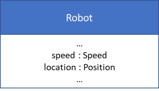
An attribute should only refer to the entity in which it is contained. This statement may seem abundantly obvious, but, in practice, it is not. A properly constructed entity would adopt the following pattern in Figure 1. In this figure, the speed attribute refers to the robot’s speed and the location refers to the robot’s position.
It is very common to roll up properties under a single entity and attempt to express the distinction in the role name of the attribute. For example, we may talk about the amount of fuel in a fuel tank as follows:
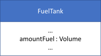
In Figure 2, we have attempted to apply the volume attribute to fuel. How should this be read? The amount of fuel in the fuel tank, or the volume of the fuel tank? The ambiguity is introduced by the role name on the attribute. “Amount Fuel” seems to be applying the volume attribute to the fuel and not to the fuel tank.
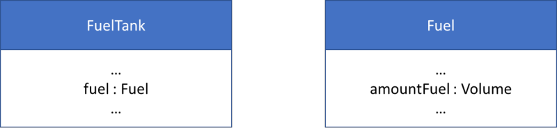
By applying this best practice and refactoring, a much clearer model emerges in Figure 3. We did not even need to rename the “amount fuel” attribute since the semantic is now aligned with the entity in which it is composed.
Role Names should not Matter
The fact that role names should be immaterial is a necessary corollary to the previous best practice. If the role name provides additional context, or if it is paired with another noun (e.g., amountFuel), then it likely violates the first best practice.
In an ideal situation, the names of all attributes could be removed, and the model would maintain its meaning and lose none of its utility.
Core Patterns
Over the course of many years of developing data models and interface documentation, several common challenges kept appearing. These problems commonly occur and, as with software design patterns, benefit from a general, reusable solution.
An understanding of these patterns helps when looking at a model. This allows users to promptly identify how the models may be used and supplements the context provided by the data models themselves.
The Command Pattern
There is a distinct difference between command and status, but they are often modeled with the same semantic.
Imagine placing a kettle of water on the stove and turning the stove eye on high. The water does not boil instantly. Although the desired temperature may be “boiling,” the water’s current temperature is not the same thing as the water’s “commanded” temperature.
This pattern consists of an association that connects the entity issuing the command and the entity being commanded. The role names on the participants are important as they indicate which entity is playing which role (commander or commanded).
Role names really should not matter, but we are applying a convention to make modeling easier. The main idea is to make sure the role name clearly differentiates the two roles in the relationship.
This pattern is constructed using a simple noun-verb-noun language analog. The first noun is the subject (commander), and the second noun is the direct object (thing being commanded).
This pattern is designed so that it “stacks” with other commands in recognition that it is possible to have multiple layers of commands. This construction also allows for the possibility that a command may be rejected.
Consider an autopilot sending a vehicle to an altitude of 500 meters. The vehicle could be commanded to fly to 500,000 meters. An intelligent autopilot could easily reject that command, thus introducing a third altitude: the desired altitude (500,000 m), the commanded/target altitude (500 meters), and the current altitude (value not specified in the example).

When to Use Pattern.
The Command Pattern should be used when there is some entity being commanded by another entity. The association provides context for the command. It may include the time the command was issued.
Explanation of Diagram
Figure 4 shows an example of the command pattern. `ControllingEntity_Commands_ControlledEntity` indicates the commands that are issued directly to the ControlledEntity by the ControllingEntity.
The Observer Pattern
It is very common for one entity to be observing another. There is a difference between the actual position of an entity and its observed (or sensed) position.
The Observer Pattern consists of an association that connects the observer and the entity being observed. The role names on the participants are important as they indicate which entity is playing which role (observer or observed).
This pattern is constructed using a simple noun-verb-noun language analog. The first noun is the subject (observer), and the second noun is the direct object (thing being observed).
When to Use Pattern.
The Observer Pattern should be used when there is some entity being observed by another entity, when such a distinction is necessary. There may be applications in which the “sensed position” of a platform is sufficiently equivalent to the “actual position” of the platform. Those instances would not benefit from this pattern.
The association provides context for the observation. It is possible that the observer is the same type of Entity as the observed. In all cases, there is reliance on the role names (observer, observed) to fill in the context correctly.
Note: The observation itself does not have a position — this is a common mistake that seems to run us down modeling dark alleys. See “Dynamically Shifting Perspective.”
Explanation of Diagram.
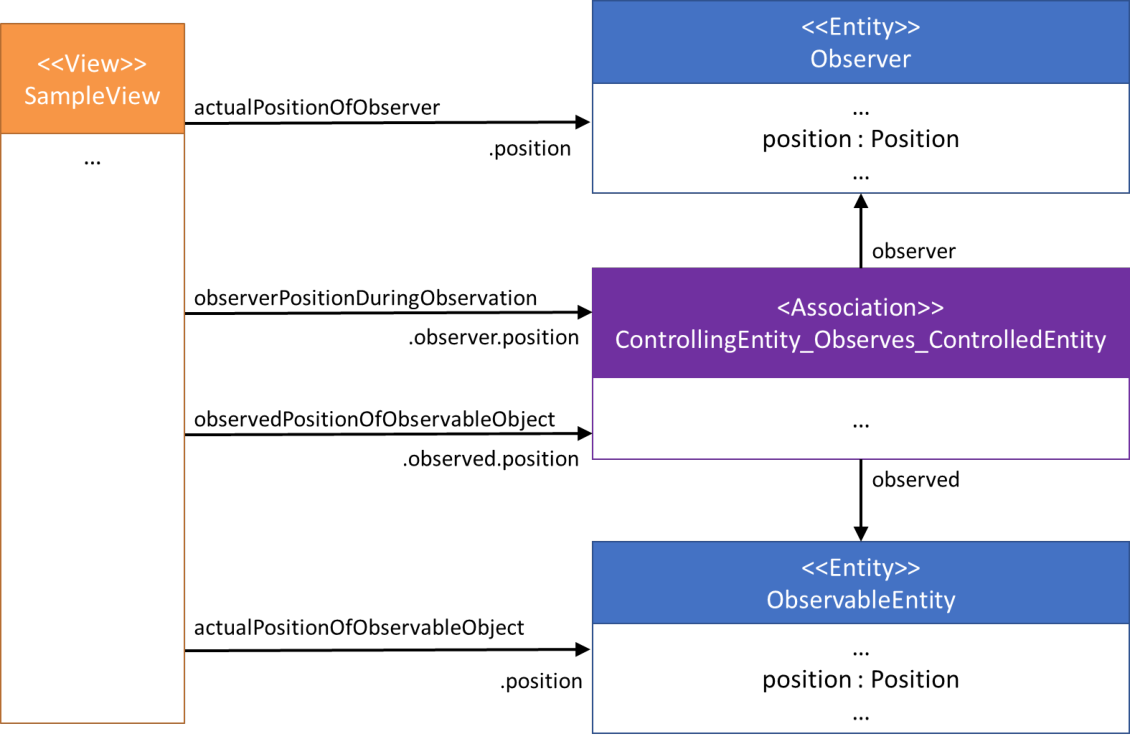
Figure 5 shows an example of the Observer Pattern with four different semantics documented. The projections directly to Observer and ObservableEntity should be understood as any typical projection — namely position of Observer and position of ObservableEntity, respectively. The other projections should be in the context of the observation (the association) itself.
The path through the model from the Observation to the Observable Entity’s position should be read as “the Observable Entity’s position in the context of the Observation.” In other words, the observed position of the Observed Entity.
The path through the model from the Observation to the Observer’s position should be read as “the Observer’s position in the context of the Observation.” This is a little more difficult to understand since it is necessary to consider what the role of the observer is in the relationship. Thus, this represents the position of the Observer when it makes the Observation.
Note: It is valid (but not necessary) to represent the observed position by explicitly adding the Observer to the context. This would be read as “the position of the Observed Entity as observed by Observer.” This semantic is implicit when using the Observe association.
The Specification Pattern
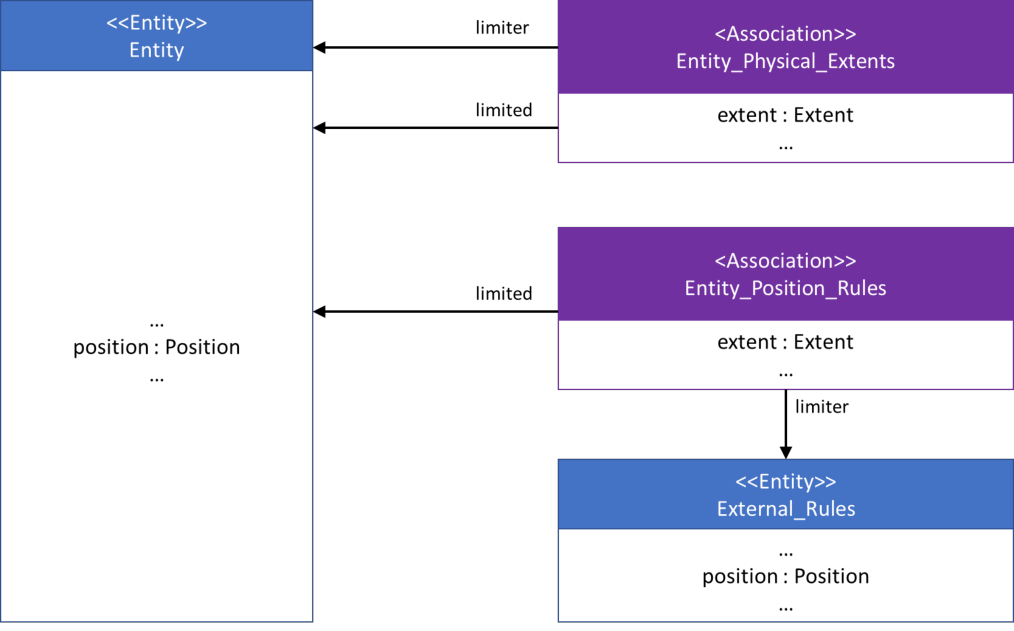
Specification is intended to express the idea of limiting a range of values. Since there may be many reasons that a value may be limited, there may be many instances of this pattern applied to an entity.
Consider an Automobile entity. The capacity of its fuel tank could restrict travel to 300 miles. However, the vehicle could also be prohibited by its owner from being more than 20 miles from home. Thus, there are two different types of specifications — one that is a physical limit of the system (fuel tank) and one that is an externally imposed rule. As anyone who has ever been a teenager knows, there might be a Really Good Reason™ to exceed that 20-mile limit, but it would be difficult to ignore the physical limit (without refueling).
This pattern consists of an association that connects the entity causing the limit and the entity being limited. The role names on the participants are important as they indicate which entity is playing which role (limiter or limited).
This pattern is designed so that multiple specifications can be used in parallel and even applied to existing patterns (e.g., command).
When to Use Pattern.
The Specification Pattern should be used when there is a need to describe the limits of an entity’s attribute(s).
Current Shortcomings.
As formulated, this pattern lacks a description about the minimum and maximum values of the extent it is capturing. This pattern currently uses the observable “extent” and delegates the definition of minimum and maximum to the logical level. This needs to be stacked with an appropriate Min/Max Pattern once defined.
Explanation of Diagram.
Figure 6 illustrates two examples of the specification pattern. The `Entity_Physical_Extents` indicates the physical (internal) limitations of the Entity, while the `Entity_Position_Rules` indicates a mission-based (external) limitation. It is also possible to compose the physical limitation back into the Vehicle since it is a defining characteristic of the entity.
The Uncertainty Pattern
The Uncertainty Pattern emerges from the realization that the actual value of an attribute may be different from the observed value of an attribute. The ability to accurately capture a value is limited to the capabilities of the sensors being used, and it is occasionally necessary to capture this uncertainty.
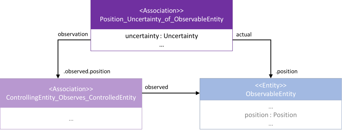
The uncertainty itself is contained by an association that relates the two contexts of the attribute. Were the uncertainty attribute added to the entity itself, it would be read as the “uncertainty of the entity.” This is not the intent. This pattern exists to resolve that ambiguity.
This pattern consists of an association that points to the same attribute in two different contexts. The uncertainty is contained by the association itself since it represents the relationship between these two aspects of the attribute. One of the participants should point to the “actual” value while the other points to the “observed” value.
Although shown as building upon the Observer Pattern, the Uncertainty Pattern will have other usages.
Note: It is reasonable to use this general pattern to capture the uncertainty between any two related measurements which may have a resulting uncertainty (i.e., it is not limited in application between a measured value and an actual value).
When to Use Pattern.
The Uncertainty Pattern should be used when it is necessary to represent the concept between actual and observed values. A generalized version of this pattern can be used to apply any observable as a property of another attribute (e.g., the validity of an entity’s position).
Explanation of Diagram.
Building upon the Observer Pattern (elements shown in faded colors), the participants on the uncertainty association use the path properties to further specify the context of the relationship. “Actual” refers to the actual position of the entity while “observation” refers to the “observed” position of the entity.
The Associated-Observable Pattern
In the Shared Data Model, there are several Observables described as only being valid within an association. These are the so-called “associated observables.”
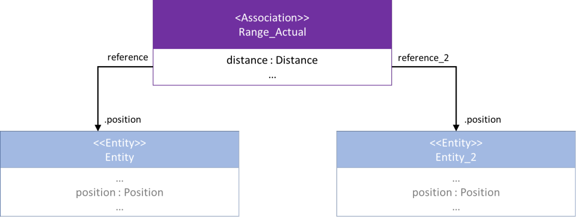
This pattern demonstrates a way to model one such observable. This example will use distance. It is, effectively, an operation on the positions of two different elements.
This pattern consists of an association that connects the two entities for which the range is desired. The role names on the participants are not as important as with other patterns, since the range may or may not be subject to a perspective. That is, the distance between two points is the same regardless of whether the measurement was made from A to B or from B to A.
When to Use Pattern.
The Associated-Observable Pattern should be used when it is necessary to document a relationship that only exists between properties of two (or more) entities.
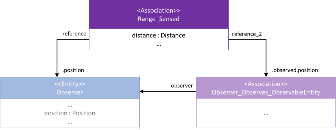
It would also be possible to build upon the Uncertainty Pattern to capture the “sensed distance between observed and the observed entity’s position,” as illustrated in Figure 9.
The Wrap
Do you remember a time when you learned something that totally turned your understanding of the world upside down? In elementary school, I was exclusively taught that leap years occurred every four years. I was never taught about the “century rule.” Fortunately, this is not something I worry about on a daily basis, but imagine my surprise when the discussion arose in a computer science class about calculating leap year. I had an incredibly simple solution while some of my classmates were discussing additional terms and complications. I felt like I had been lied to my entire life — there was this definition of something so simple that everyone (except me) understood.
This must have been what physicists felt like once Einstein introduced the Theory of Relativity. For the most part, the Newtonian Model of the world works well, but it starts to break down at relativistic speeds.
These patterns should be considered in a similar manner. They may not be universally applicable. They may apply particularly well for a set of problems and not for others. These patterns exist for the sake of making data models more useful, more readable, and more understandable.
If the application of these patterns works against these objectives, their use should be seriously reconsidered in your project. On the other hand, imagine receiving a data model that is built with a series of easy-to-read patterns. Imagine the utility that such a data model could provide not just for your organization, but for the larger integration community.
Acknowledgements
This paper would not be possible without the input of many members of the modeling community. We have been working on different versions of patterns for years, and many of the following individuals have contributed to our thinking and refinement of these ideas. We would like to send out heartfelt thanks to: Dr. William G. Antypas, Dr. James “Bubba” Davis, Bill Kinahan, Dave Lombardi, Stu Frerking, Nathan Flinn, Joey Wilson, Melvin McDaniel, Dmitry Slavnikov, and Nick DeTello.
References
- Newton, Elizabeth Louise. 1990. *The rocky road from actions to intentions.* PhD diss., Stanford University.